- Blog
- Networking
- Post
Configuring UCS Service Profile Templates – vNIC/vHBA Placement Policies – Part 2
Overview
In Part 1 of this 2-part series we discussed initial configuration of Cisco UCS Service Profile Templates. In this second and final part of our series on creating service profile templates, we discuss configuration of Cisco UCS vNIC/vHBA Placement Policies.
vNIC / vHBA Placement Configurations
Placement Policies is a relatively new feature in UCSM. The long and short of it is, this becomes important in two areas:
- If you’re moving from, say, different blade types with different adapters like full to half or half to full, or one adapter to two adapters; or
- If you’re using that vNIC connection with VMWare where you’re going to create 16 new NICs.
And so what you want to do here is make sure that your set devices like your HBAs and your hard set vNICs come before those dynamic vNICs. So then you set placement.
You can just set it to Let System Perform Placement, which is the default. But you also have other options, like you can choose any of the placement policies you may have already created.
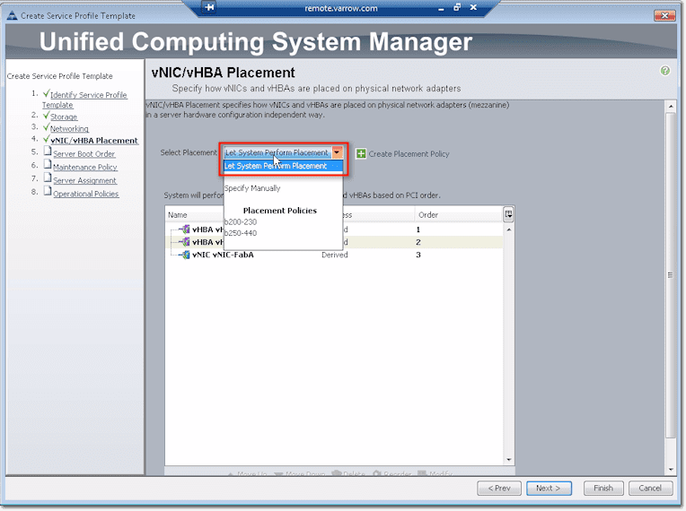
To create a Placement Policy from here, just click Create Placement Policy. This will bring up the Create Placement Policy dialog box. You can then just move things around and tell the system where you want the slots to assign. For example, you can say Exclude Dynamic. This means, dynamic does not get placed up front.

The system allows you to set PCI order. So that when the system boots up, your devices are in the same order. Things like VMWare really care about PCI order, so that’s an important thing to do when you set this. Click Next to proceed to Server Boot Order configurations.

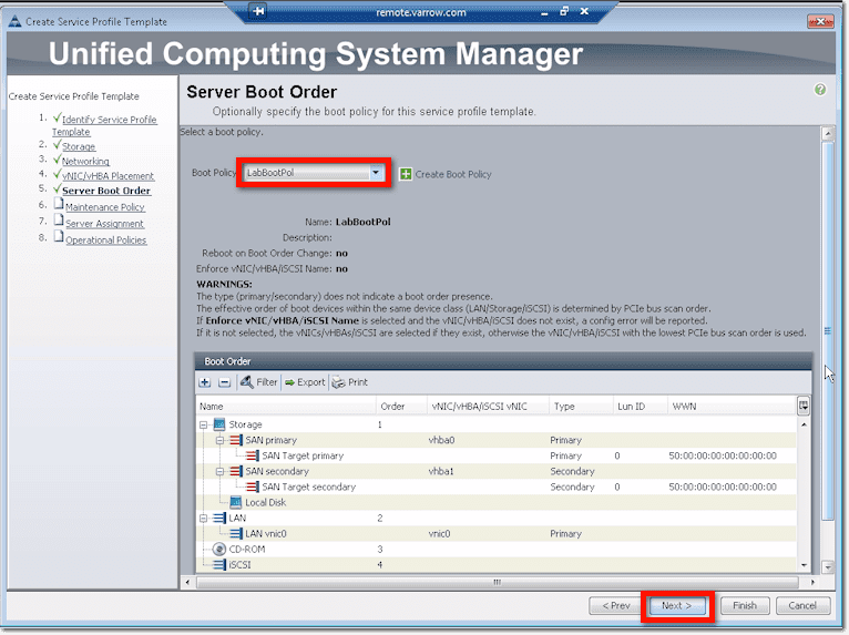
Server Boot Order Configurations
This is where you specify what you want to boot from. Just like in the other sections, you can either select an existing Boot Policy from the drop-down list or you can create a new one by clicking Create Boot Policy.

Here’s what you’ll see if you click Create Boot Policy.

Give your boot policy a name and (if you want) a description.
Check the Reboot on Boot Order Change checkbox if you want to reboot all servers that will be using this boot policy each time you make changes to the boot order. You can also check the Enforce vNIC/vHBA/iSCSI Name checkbox if you want to enforce naming schemes. Otherwise, just leave these checkboxes to their defaults, which is unchecked.

The next step is to tell UCS how you want to boot. So, for instance, if you want to boot from SAN, just click the Add SAN Boot link found inside the vHBAs panel. Then when the dialog box pops-up, you specify which vHBA (e.g. “vhba0”) and whether you’re adding a Primary or Secondary path. Let’s say you’re adding a Primary, so click its corresponding option button. Click OK when you’re done with all that.

That newly created SAN boot will then be added to your Boot Order list.

But there are still other things you need to set, like your LUN ID and the WWN. To set those, click the Add SAN Boot Target link, which is located right below that Add SAN Boot link you clicked earlier.
When the Add SAN Boot Target dialog box appears, specify the Boot Target LUN. This is normally set to zero. Then type in your initiator in the field labeled Boot Target WWPN. Usually, you just enter the desired value (e.g. 50) right before the first colon and then leave the rest unchanged. Click OK.

If you want to set up a Secondary, repeat the same steps you took in creating that first SAN boot. Of course, you need the specify another vHBA (e.g. “vhba1”) and select Secondary from the option buttons. Click OK.

Again, that Secondary SAN boot will be added to the Boot Order list.

Just like you did earlier, you need to add a SAN Boot Target. However, because you already have a Primary and a Secondary, once you click the Add SAN Boot Target link, the system will ask you to choose which SAN boot the SAN Boot Target should be added to. Select Add SAN Boot Target to SAN secondary.

Then do pretty much the same thing as you did earlier.

So now you have your Primary and Secondary, which will give you two options when you do SAN boot.

But that’s only for SAN boot. You can actually come up with a combination of boot options. So you can add LAN Boot, Local Disk, CD-ROM, Floppy, and iSCSI. Here’s a screenshot showing a variety of boot options:

Boot policies are very flexible. For example, you can have Boot from SAN as Primary and LAN PXE as Secondary, or you can have Primary from SAN and Secondary from CDROM. It’s completely up to you as to how you want to do it.
When you’re done setting this part up, just click that OK button at the lower-right corner of the screen (see previous screenshot).
Once you’re back in the Server Boot Order window, you may select that boot policy you just created from the Boot Policy drop-down list, and then click Next.
Maintenance Policy
Create a Maintenance Policy by clicking the appropriate link on the screen.

Give the policy a name and then pick from the Reboot Policy options listed below. Basically, by picking an option, you are telling the system what it should do every time you make a change to this profile.
- Immediate – The server will reboot automatically
- User Ack (Acknowledge) – The user must reboot the server manually
- Timer Automatic – Reboot is based on a schedule
The recommended option is User Ack, so pick that option and then click OK.

Back in the Maintenance Policy window, select the Maintenance Policy you just created from the drop-down list and then click Next.

Server Assignment
This is where you assign a server pool to this particular service profile template. Select your desired pool from the Pool Assignment drop-down list. Alternatively, if you don’t want to associate this profile template with any server pool yet, you may select Assign Later.
You’ll then be asked which power state (Up or Down) you’d like the server to have the moment the profile is associated with it. The default is Up and most admins prefer to leave it that way.

If you scroll down to the bottom of this screen, you’ll see some Firmware Management (e.g. BIOS, Disk Controller, Adapter) policy settings there. You may have to click those down arrows on the Firmware Management bar to expand that section.
There are two items in there: Host Firmware and Management Firmware.

You may select a host firmware package or management firmware package from their corresponding drop-down lists to associate that package to this service profile. Or, if you want, you may create a package by clicking on the appropriate “Create …” link.
Inside the Create Host Firmware Package dialog box, you’ll see a bunch of tabs for components like: Adapter, BIOS, Board Controller, FC Adapters, HBA Option ROM, and Storage Controller.
This is how it works. When you specify a configuration here, you’re actually telling the system that when you apply this service profile from one blade to another, it should lay down this particular configuration.
Let’s say you went into the Adapter tab, checked M81KR and selected Version 2.0(1q). Once the system lays down this service profile, it will put 2.0(1q) firmware on that M81KR. And if it gets disassociated and moved to another blade that has 2.0(1t), the system should still put down 2.0(1q).

This is particularly useful if you don’t want to worry about a firmware bug that you haven’t hit yet and you already know that this particular configuration for M81KR really works.
You can do this for all the other components you can find in there. When you’re done, click OK.
There’s one little downside to this though. When you try to update firmware using a unified firmware management tool, the system wouldn’t let you update firmware on blades. That’s because the system will see that you have a firmware policy in place and it won’t be able to override that.
So, you would then need to change your firmware policy or create one and then change it instead of doing things from that unified firmware management tool. For some admins, that’s fine because you’re changing firmware on a blade that interacts with an OS, which can be a scary proposition.
So once you already have the Host Firmware Package you want, you can select that from the Host Firmware drop-down list.
You can do the same thing for Management Firmware. If you click the Create Management Firmware Package link, you’ll see something like this:

Just apply the same procedure/principle you used when you created the Host Firmware Package.
When you’re done selecting a Host Firmware policy and a Management Firmware policy, click Next. This will bring you to the last set of configurations needed to create a service profile template.
Operational Policies
Operational policies are more like a bunch of miscellaneous settings that aren’t as important as those found in the other sections. But let’s go through each one of them quickly.
BIOS Configuration
The first item you can set here is the BIOS policy. Click the Create BIOS Policy link to create one.

Everything that you can set in the BIOS you can set in the BIOS Policy. We won’t go into the details here, but let me show you a couple of screenshots so you can see what you can find in there.


There’s actually more, but once you’re done changing some of the defaults to settings that you prefer, click Next. Again, once you apply this service profile to a blade, all those BIOS settings will be automatically set for you.
External IPMI Management Configuration
IPMI or Integrated Platform Management Interface is part of the CIMC (Cisco Integrated Management Controller) and is responsible for giving access to CIMC. To give access, you have to select an IPMI access profile from the drop-down list. If what you want doesn’t belong to the list, then you create it. Click the Create IPMI Access Profile link to do that.

Creating an IPMI access profile would entail giving the profile a name and description, as well as creating IPMI users.

Each IPMI user you create should be assigned a name, a password, and a role (Read Only or Admin).

What are the things you could do with IPMI?
If you do VMWare Dynamic Power Management, where you could bring up and shutdown hosts or blades based on need, you can do that via IPMI. You’ll need to set up access, control and all that, and you do it right there. Another management tool that uses IPMI is Wake-On-LAN.
Management IP Address
When you have pools and management IP addresses for KVM, you have an option to either assign IPs to a blade or to a service profile. This is where you specify which option you prefer. Choose None if you want to assign them to the blade and Pooled if you prefer the service profile.

Monitoring Configuration (Thresholds)
This is simply where you set thresholds for almost anything measurable in your system.

Power Control Policy Configuration
UCS has the capability to cap power. So you can do a number of things that can ensure that power is kept within a certain range.

Here’s a quick look at some of the settings included in a Power Control Policy.

Scrub Policy
A scrub policy will tell the system what it should do to local data and BIOS settings when a server is disassociated from a service profile containing this policy. Here are your options:

Select Yes for the Disk Scrub option if you want all data on the server local drives to be completely erased and No if you want them to be preserved.
For the BIOS Settings Scrub options, select Yes if you want the BIOS settings for that server to be erased and reset to the defaults associated with that server type and vendor, and No if you want them to be preserved.
That’s it. We’ve already pretty much covered all steps required for creating a Service Profile Template, so click Finish.

Before we end, let me show you first how easy it is to create profiles off of that Service Profile Template.
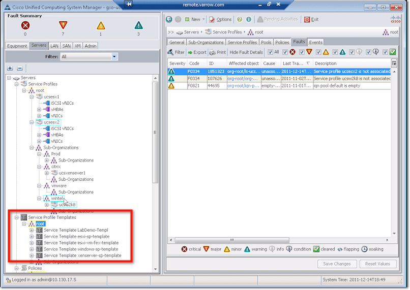
In the UCS Manager, scroll down to the Service Profile Templates node.
Now, you can either right-click on a Service Profile Template and then select Create Service Profiles from Template from the context menu …

… or click Service Profile Template and then click Create Service Profiles from Template as shown.

When the Create Service Profiles from Template dialog box appears, enter a Naming Prefix and the number of profiles you want to create. When done, click OK.

Those newly created service profiles will then be added to your Service Profiles node.

Notice that the system appends a number to the naming prefix you specified earlier, i.e. 1 for the first profile, 2 for the 2nd, and so on. They’re all enclosed in blue boxes because they are not yet associated to a service or a blade pool.
Conclusion
Well, we’re finally done talking about what you need to know to create service profile templates. These templates make it much faster to provision multiple servers that share basic parameters and have similar requirements. If you have any questions about any of the steps, please comment below.