Introduction to Network Address Translation
- Blog
- Networking
- Post
Overview
Almost anyone with a modern Internet connection has used Network Address Translation (NAT). NAT has been a big part of large scale IP network deployments since the IPv4 address space began to dwindle. At its most basic, NAT enables an internal IP address (or addresses) to be mapped to an external IP address (or addresses); this enables the use of private RFC 1918 IP addresses on internal networks while only using a single or very few public IP addresses.
This article takes a look at some of the basic NAT concepts including the types of NAT as well as how interfaces are labeled to perform NAT functions.
NAT Basics
The first thing to understand is the different types of NAT, which include: static, dynamic and overloaded.
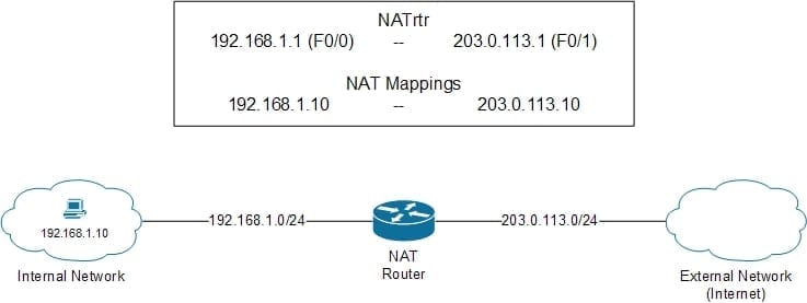
With static NAT a single specific internal IP address is mapped to a single specific external IP address; an example of this is shown in Figure 1.
Figure 1 – Static NAT
In Figure 1, a PC on the internal network needs to communicate to a host on the external network, which in this case is the Internet. Private RFC 1918 are not routable on the public Internet and would not be allowed as a source or destination address. To get around this, NAT can be statically configured to map the internal IP address 192.168.1.10 (the host) to the external IP address 203.0.113.10; if this was with all communications on the external network it would look like traffic would be coming from 203.0.113.10 instead of 192.168.1.10. In this situation NAT would refer to the IP address 192.168.1.10 as the inside local address and its mapped IP address 203.0.113.10 as the inside global address.
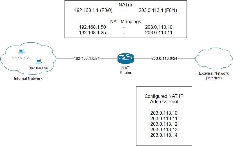
With dynamic NAT, internal IP addresses are dynamically mapped to a pool of external IP addresses; the mapping is still one internal to one external but the external address to be used as dynamic is selected from the configured pool. An example of this is shown in Figure 2.
Figure 2 – Dynamic NAT
In Figure 2, two PCs on the internal network need to communicate to a host on the external network, which in this case is the Internet. Private RFC 1918 are not routable on the public Internet and would not be allowed as a source or destination address. To get around this NAT can be dynamically configured to map the internal IP addresses 192.168.1.25 (host) and 192.168.1.50 (host) to IP addresses in a configured NAT IP pool. In Figure 2, the mappings show that the host with the IP address 192.168.1.50 was mapped to 203.0.113.10 and the host with the IP address 192.168.1.25 was mapped to 203.0.113.11; what this means is that the host with an IP address of 192.168.1.50 initiated external traffic first. In this situation NAT would refer to the IP addresses 192.168.1.25 and 192.168.1.50 as the inside local addresses and their mapped IP addresses 203.0.113.10 and 203.0.113.11 as the inside global addresses.
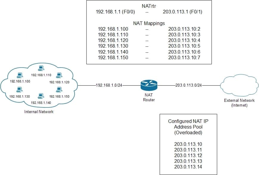
With overloaded NAT (also called Port Address Translation (PAT)), the one to one mapping being used with static and dynamic NAT is not used, what is used is a many to one (or many) relationship. Instead of an external IP address being assigned per internal IP address, a single external IP address is used by all internal IP hosts and mapped by individual port number to the external IP address. Only when the available number of port numbers used by the external IP address is exhausted is a second external IP address used in a similar way (if configured, many times only a single external IP address is used). An example of this is shown in Figure 3:
Figure 3 – Overloaded NAT (PAT)
In Figure 3, there are six different internal hosts that are accessing external hosts and overloading NAT is configured with a pool from 203.0.113.10 through 203.0.113.14. Assuming that traffic can through the NAT router sequentially they would each be mapped to an external IP address (in this case the first in the list – 203.0.113.10) and a specific port number.
In each one of these examples, the NAT router is configured with the same IP addresses; 192.168.1.1 on the Fast Ethernet 0/0 interface which is labeled as the Inside NAT interface and 203.0.113.1 on the Fast Ethernet 0/1 interface which is labeled as the Outside NAT interface.
Summary
There are more complex ways to deploy NAT but the purpose of this article was to introduce NAT and how it functions in a simple environment example, which also happens to be a very common implementation. Hopefully the content of this article will provide the ready enough information to help in their understanding of NAT and how it can be used on a network.


