Overview
The vNetwork Distributed Switch (vDS) streamlines the process of setting up virtual machine networking by providing you with a centralized point of control for provisioning, administration and monitoring through vSphere’s vCenter. In today’s video and how-to article, vExpert Jason Nash walks you through the configurations required to setup a new vDS in your vSphere environment.
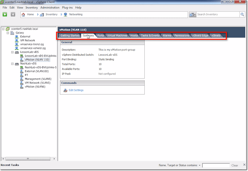
vCenter vDS – Summary Tab
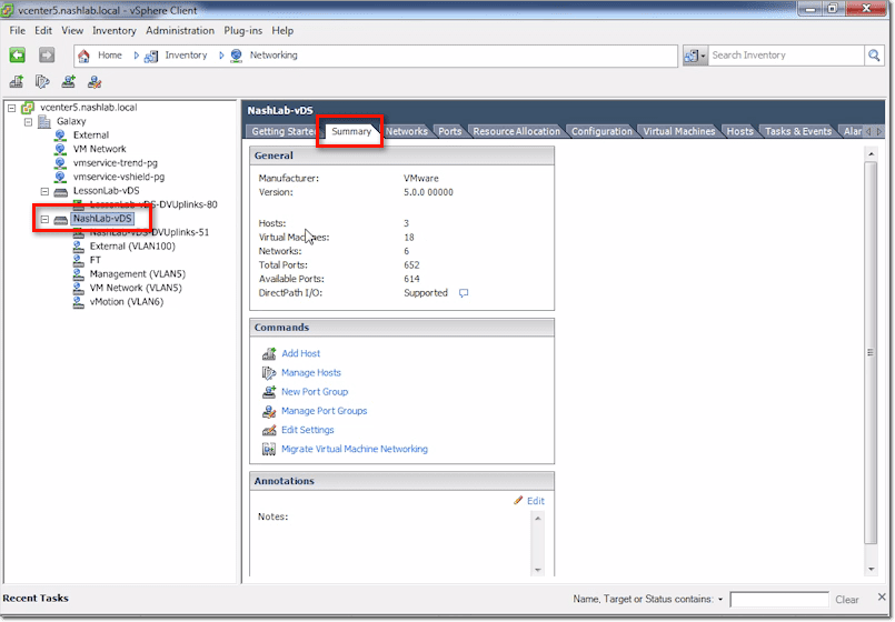
The Summary tab is where you’ll find information telling you the number of hosts, number of VMs, number of networks, total ports, available ports, and so on. As you start rolling out hosts and VMs, those numbers will go up.
vCenter vDS – Networks Tab
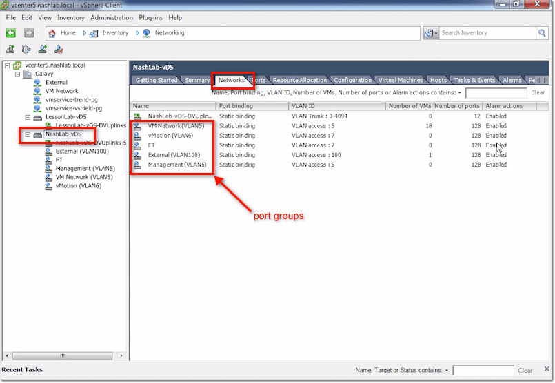
The Networks tab contains all your networks, which equate to port groups. Other information includes port binding, VLAN ID, number of VMs, number of ports used, and whether alarms are enabled.
vCenter vDS – Ports Tab
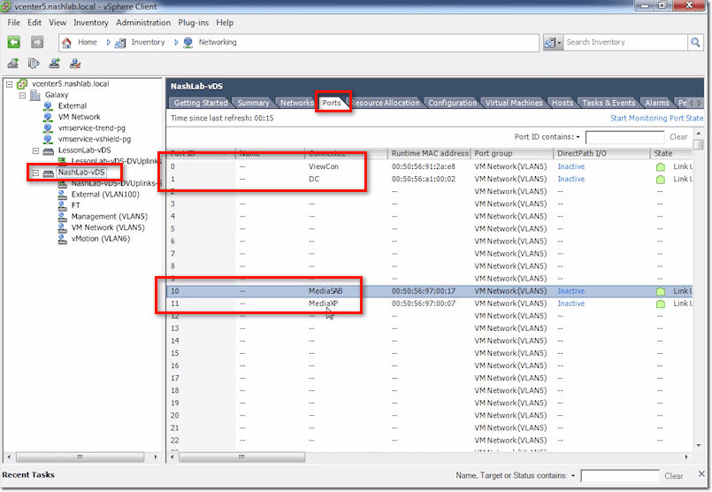
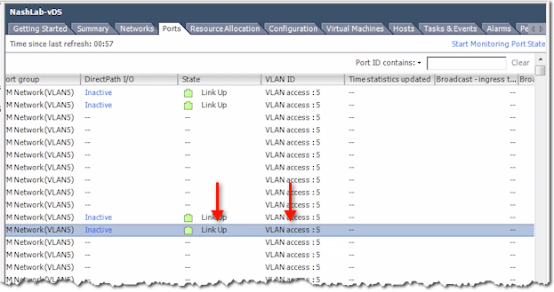
This tab contains vital information related to Port Mirroring and Netflow. When you plug a VM into a vSwitch or a VMs NIC into a vSwitch (as a VM may have multiple NICs), it gets assigned a port. That is, a port ID on the distributed switch.
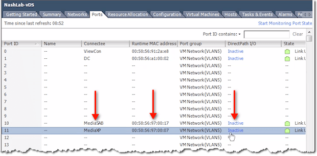
So, for example, MediaXP is assigned Port 11, while Media SAB is assigned Port 10. Domain Controller (DC) is Port 1 and ViewCon is Port 0.
One scenario wherein these port IDs are going to come in handy is when you’re doing some troubleshooting concerning Port Mirroring and Netflow. That’s because those two reference these port IDs.
So, for instance, you notice that Port 11 is sending a whole lot of traffic. You can go in here and see what Port 11 is. Then you can check what its corresponding VM is, what its MAC is, and what its DirectPath I/O is.
You can also see whether the link is up and which VLAN it corresponds to.
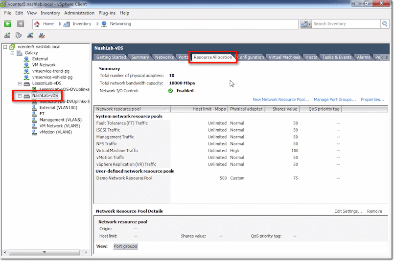
vCenter vDS – Resource Allocation Tab
This is where you configure Network I/O Control and other related stuff.
vCenter vDS – Configuration Tab
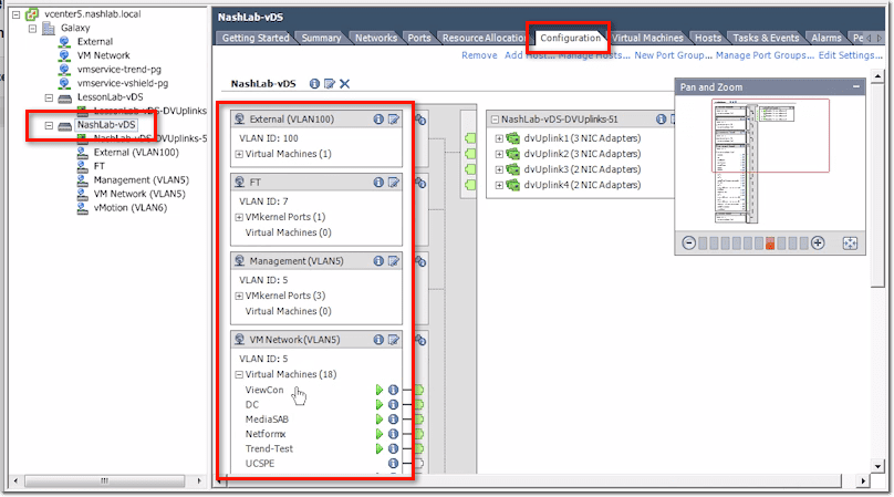
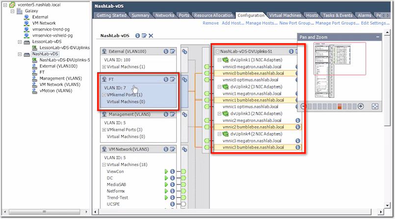
The Configuration tab features a GUI showing your current configuration. On the left are your port groups and any VMs you’ve got plugged into them.
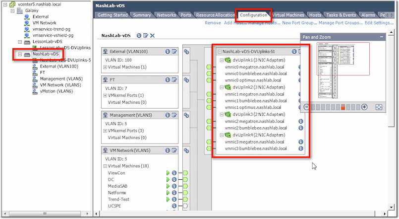
Then on the right are your physical uplinks, which vmnic is plugged in, and which servers they are.
Now, if you click on a port group (e.g. FT), it will show you which physical uplinks are being used.
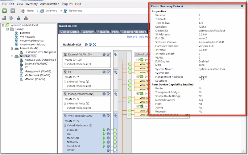
Also, if you click on an “i” icon (enclosed by a blue circle) on the right side, you’ll be able to pull up say CDP for Cisco or LLDP for non-Cisco.
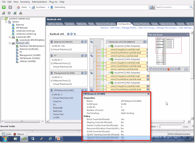
On the other hand, if you click on a similar “i” icon on the left side, you’ll get basic information about the port group in question.
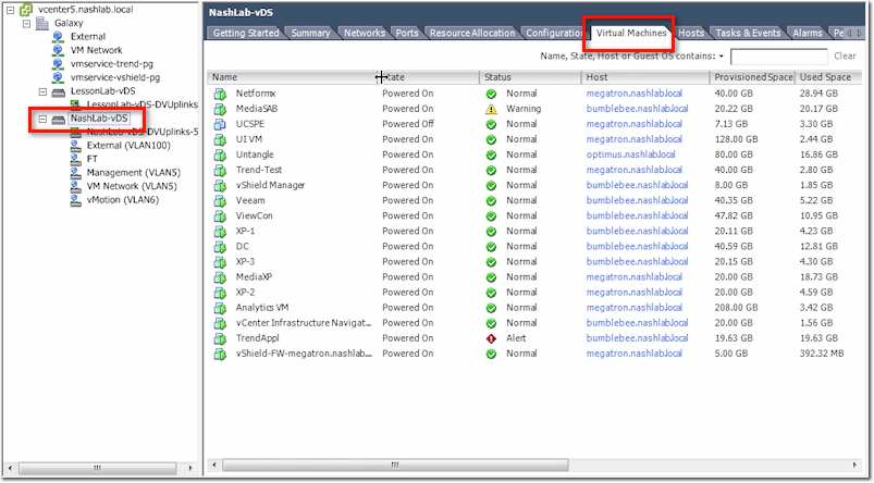
vCenter vDS – Virtual Machines Tab
This tab will just show you all the VMs that are using your distributed switch.
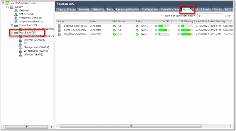
vCenter vDS – Hosts Tab
Similarly, this will show you all the hosts using your distributed switch.
The rest of the tabs include Tasks & Events, Alarms, and Permissions.
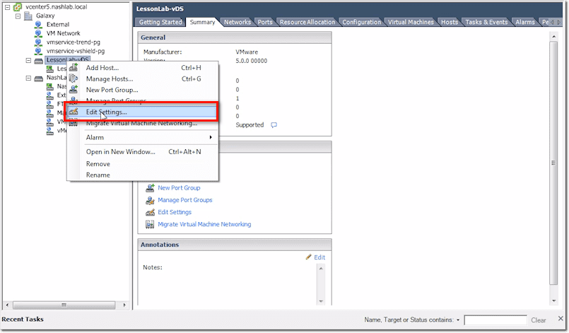
Now let’s look at the main options for the main switch. We right-click on the main switch and select Edit Settings from the context menu.
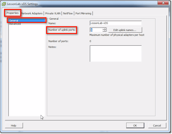
vDS Settings – Properties Tab
In the General section of the Properties tab, you can set the number of uplink ports.
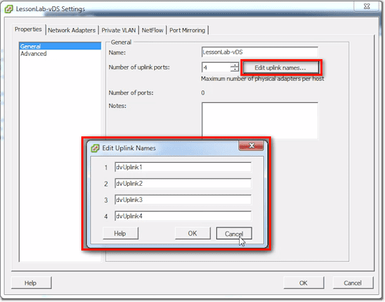
You can also edit the uplink names by clicking on the Edit uplink names button and then changing the uplink names you find in the window that pops up. Notice that there are 4 boxes in our screenshot. That’s because we have 4 uplink ports. The number of boxes will always be equal to the number of uplink ports.
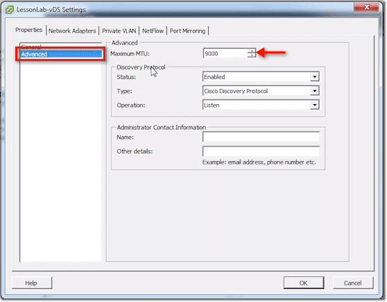
In the Advanced section, one thing you can set there is the Maximum MTU. If you want to do Jumbo Frames (9000-byte frames), you can set it right here.
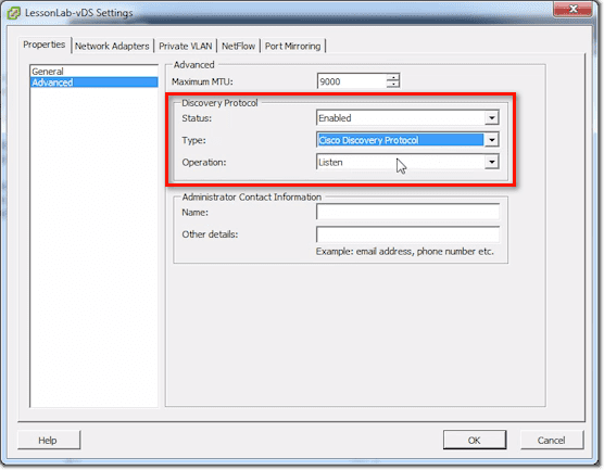
You can also enable the Discovery Protocol and then set the type to either CDP (Cisco Discovery Protocol) or LLDP (Link Layer Discovery Protocol). In addition to that, you can set its Operation to Listen, Advertise, or Both.
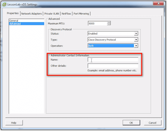
Finally, you can enter some Administrator contact information, such as the Name and other details like email address, phone number, etc. This can show up in CDP or other similar protocols.
vDS Settings – Network Adapters Tab
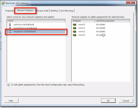
Here, if you select a host on the left, it will show you vmnics on the right and how they match up with the uplink numbers.
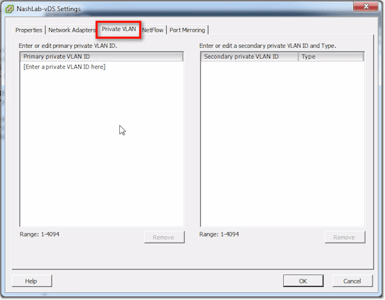
vDS Settings – Private VLAN Tab
This is where you configure stuff like Layer-2 Segmentation or VLANs within VLANs.
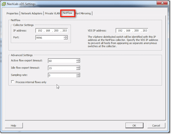
vDS Settings – Netflow Tab
This is where you configure the system to send IP statistics to what’s known as a NetFlow collector.
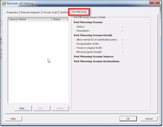
vDS Settings – Port Mirroring Tab
These settings allow you to do traffic sniffing.
Those are your main switch settings.
vDS Uplink Port Group Settings
Then you have what are called Uplinks. For the distributed switch, you only have one set of uplinks. This is in contrast to, say, the Cisco Nexus 1000V, which does allow you to have multiple uplink groups. You may have one uplink group connected to a DMZ network and a second one connected to the production network.
The DMZ uplink group cares about all the VLANs in the DMZ. The one for the production network cares about the VLANs found there. You can’t do that with the vSphere Distributed Switch. If you have a DMZ network and a separate physical production network, you’ll need to segment that, but you only have one uplink group in each vDS.
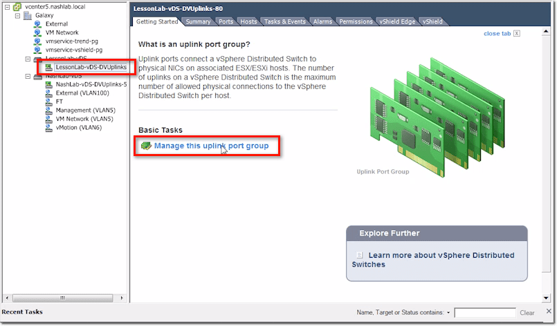
Let’s now see what we can set for uplinks. You can get to those settings by clicking the Manage this uplink port group link.
vDS Uplinks – General Section
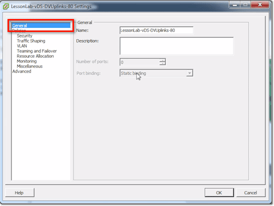
The General section is where you set the uplink’s name. It’s also where you put in a Description, Number of ports, and the Port binding option.
vDS Uplinks – Policies Section
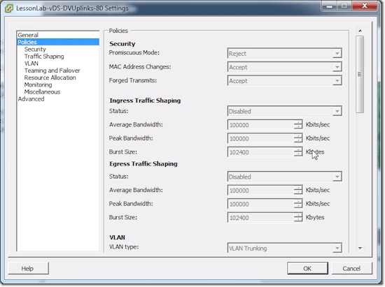
This is where you’ll see a whole bunch of policy settings, including: Security, Traffic Shaping, VLAN, Teaming and Failover, Resource Allocation, Monitoring, and Miscellaneous. The items in the subsections (e.g. Security, Traffic Shaping, etc.) are exactly the same items you’ll see in the main Policies section, except that they’re just grouped accordingly.
One thing to take note of is that most of the items are going to be uneditable. That’s because they’re mainly going to be set at the port group level.
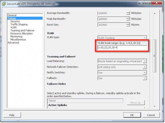
There are still a couple of things you can set. One of them is the VLAN trunk range. The default for that setting is 0 – 4094, meaning, everything. That includes tagged and untagged VLANs. If you follow your security best practices, you should only be configuring this for VLANs that the switch should actually expect to see on the physical world.
Most people leave the setting to the default (0 – 4094), but you can actually set it as shown in the screenshot.
vDS Uplinks – Advanced Section
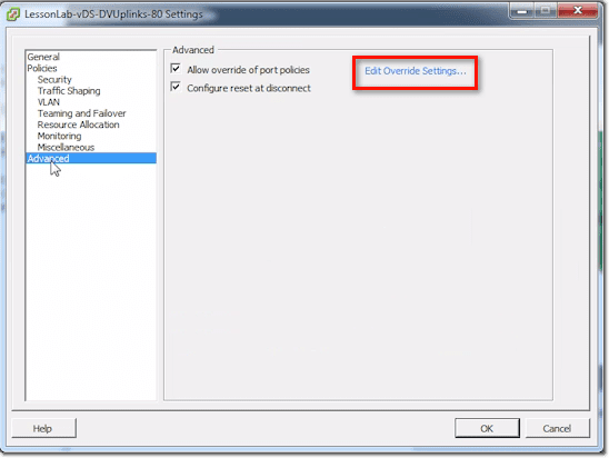
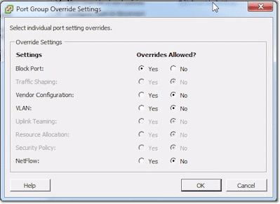
In the Advanced section, you can allow the system to override certain port policies. You specify which policies can be overridden by clicking the Edit Override Settings link.
Then as you can see, you simply choose either Yes or No if you want to allow or disallow overrides for a particular item.
Basically, there are a lot of things under the uplink settings. But really, the only thing you’ll ever set there is the one concerning VLANs.
Creating a New Distributed Port Group
Let me show you now how to create a new Distributed Port Group.
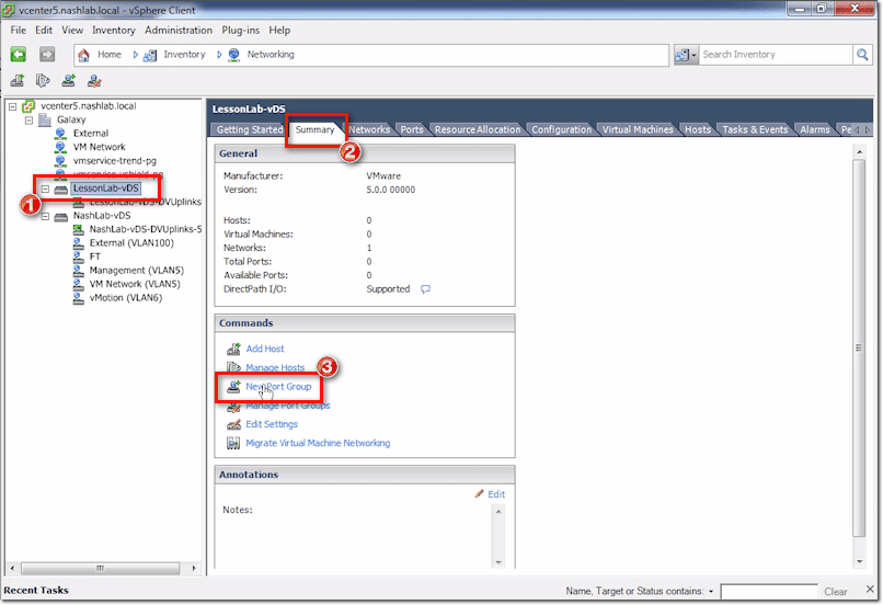
Just select the main switch and then click New Port Group under the Summary tab.
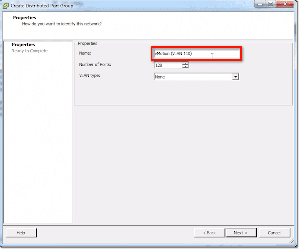
Give that port group a name.
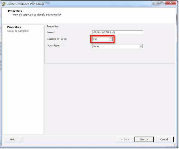
Next, assign a number for the Number of ports. Remember that when you plug in a VM’s NIC, a VM kernel, or something like that, and then you attach it into one of these port groups, it uses a port.
Make sure you set that number to something reasonable. For instance, vMotion might only need 1 port per server. So for that, you can probably set 10 or even 5 and still be OK. If you’re setting for production VM traffic and that particular VM had a /24-network, you might have to put 256 in there.
Just don’t go crazy. Don’t set it to some wacky number like 1024 when all you’ve got is a /24 network. You’re going to use up more ports as you go, and you don’t want to get to that 30,000-limit right away.
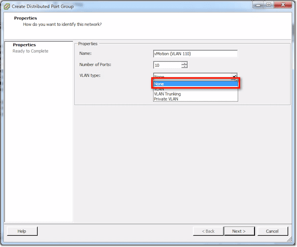
For the VLAN type, the choices are None, VLAN, VLAN Trunking, and Private VLAN. None means un-tagged.
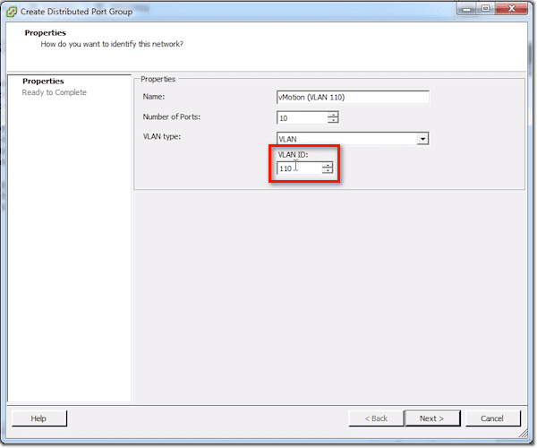
VLAN means that as a frame leaves this distributed switch, it’s going to stick a tag unto it for the VLAN number, and the uplink switch is gonna expect those frames to be tagged.
So for instance, in my case, I would set the VLAN ID to 110.
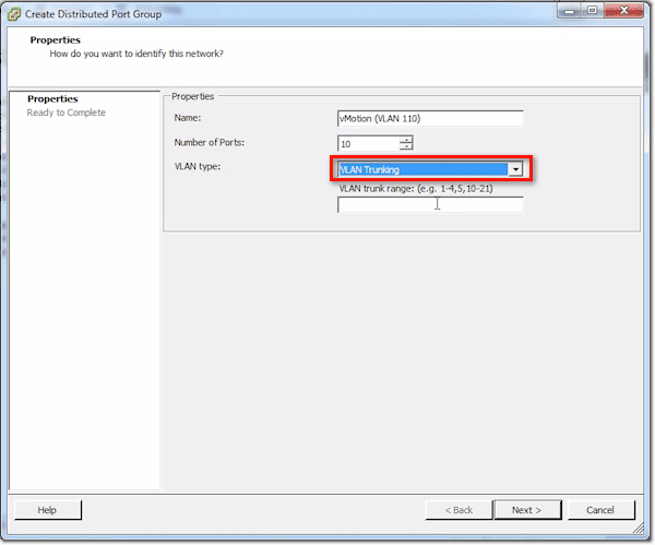
Another option is VLAN Trunking. So if I want to do a trunk, I set VLANs up to my VMs. My VMs are going to expect to see tagged frames. They can have that special guest tagging driver installed.
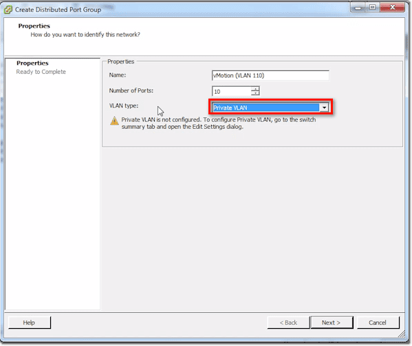
Finally, there’s Private VLAN. If you see a notice saying Private VLAN is not configured, you then have to configure it in the main switch. Once you’re done with that, you go back here and set the relevant options.
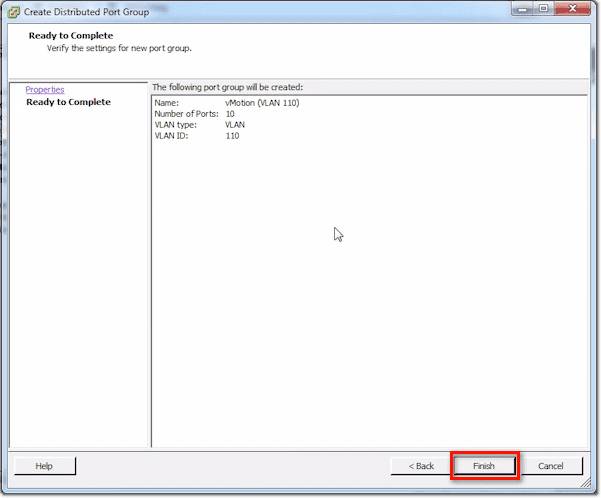
After you click Next, you’ll be shown a summary of the things you just set. Click Finish to proceed with creating the port group.
Configuring a New Distributed Port Group
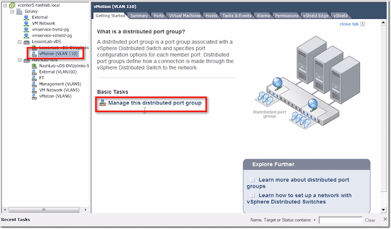
Now, let’s say you want to configure some settings. Select that newly created port group and then click Manage this distributed port group.
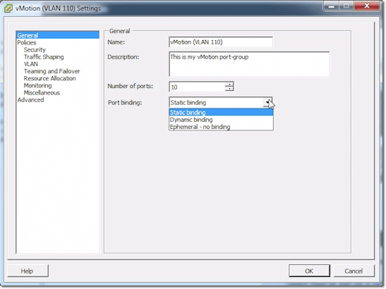
The first settings you can specify, which are found in the General section, are the Name, Description, Number of ports, and Port binding type. Port binding type can be set to either Static, Dynamic, or Ephemeral. This has to do with how it assigns those port numbers that we just talked about. Mostly, you’re going to leave that on Static.
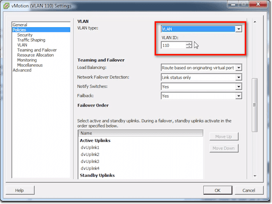
When you proceed to the Policies section, you’ll notice a lot of familiar settings. You’ll see the policy settings for Security, Traffic Shaping, VLAN, and so on.
Here’s where you change your VLAN tagging information and number.
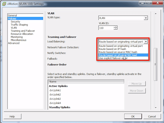
Here’s your Teaming and Failover, set at the port group level. This kind of confuses people because they think you set this at the uplink level. The answer to that is, No. You don’t, because you may do different hashing types and things like that. This depends on the type of traffic and the port group.
By default, it’s just going to be set like a standard vSwitch, and that is Route based on originating virtual port ID. There are actually several options, like:
- Route based on IP hash;
- Route based on source MAC hash;
- Route based on physical NIC load; and
- Use explicit failover order
Route based on physical NIC load is what is known as Load-based Teaming, which is the coolest one because it really looks at the NICs’ load.
All the rest, including Network Failover Detection, Notify Switches, Failback, and others, are standard VMware vSwitch settings.
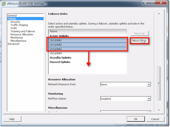
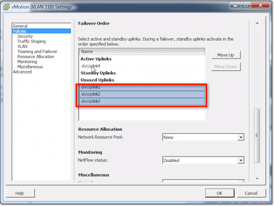
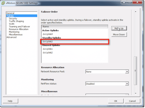
In the Failover Order list, you can do things relevant to Traffic Separation. For example, if we just want to just use dvUplink4 for vMotion traffic, we can select dvUplink1, 2, and 3 and then click the Move Down button until they’re under the Unused Uplinks.
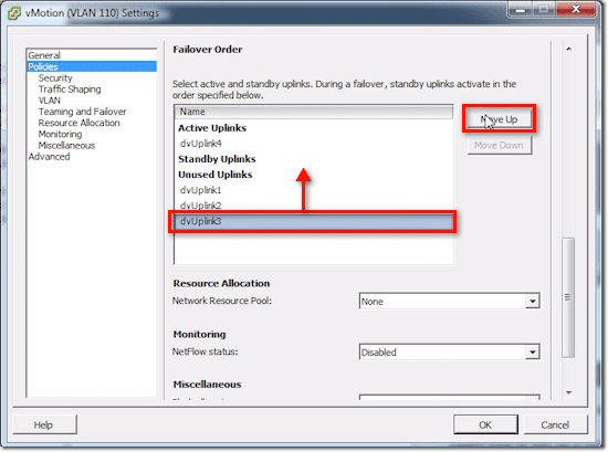
Or we can select dvUplink3 and move it to Standby Uplinks.
Once you’re done, you just click OK and the changes you made will be automatically saved.
The tabs you see for that port group are basically just the same ones you saw in the main switch, except that they’re specific to the port group for certain things.
Conclusion
Well, that’s it. We’ve gone through nearly all the settings for the main switch, uplinks, and port groups, and so we’re done. See you again next time.


