One of the most important concepts to understand when implementing voice over networks on Cisco equipment is the concept of dial peers and call legs. This article discusses this concept and reviews the configuration steps required for implementation.
A call leg is a logical connection between two routers or between a telephony device and a router. From the perspective of the originating router and the terminating router, there are two call legs for a total of four; an example of this is shown in Figure 1:

A dial peer is the physical implementation of a call leg, and as stated in the last paragraph, there are two call legs and thus two dial peers to be configured on each router. Depending on the type of call leg, there are two different types of dial peers that can be configured; these include:
- Plain Old Telephone System (POTS) – This type of dial peer defines the characteristics of a traditional telephony connection. Typically, a POTS dial peer is associated with a voice port connecting to the PSTN, PBC or telephone.
- Voice network – This type of dial peer defines the characteristics of a packet connection. There are several different types of voice network dial peers that can be configured including VoIP, VoFR and VoATM.
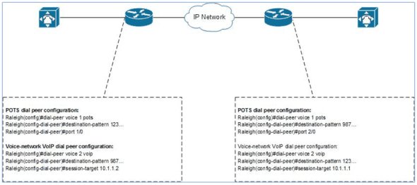
Figure 2 shows an illustration of an example POTS/VoIP dial peer implementation:

There also needs to be a method of defining how to match a specific dialed number with the correct dial peer. The most basic way to do this is by defining a destination pattern that is used to match the specific telephone numbers with a dial peer.
Basic Dial Peer Configuration
Figure 3 shows an example of a simple configuration between two offices that are directly connected. It shows that the Raleigh branch office handles all phone numbers that start with 123 and shows that the Dallas headquarters handles all phone numbers that start with 987, using 7-digit phone numbers. From the perspective of the Raleigh router, there is a POTS connection that connects to their PBX and a VoIP connection that connects to the Dallas router. From the perspective of the Dallas router, there is a POTS connection that connects to their PBX and a VoIP connection that connects to the Raleigh router.

Based on these connections, each router must be configured with two dial peers each, one POTS and one voice network VoIP.
When creating or modifying dial peer configuration, the dial peer voice command is used; the complete command syntax is as follows:
router(config)#dial-peer voice number [pots | voip | vofr | voatm]
A POTS dial peer is associated with a specific port depending on the configuration; the command syntax used for this is as follows:
router(config-dial-peer)#port port
When configuring a voice-network VoIP dial peer, the terminating routers IP address is used to associate the dial peer with a remote device. The command syntax used for this is as follows:
router(config-dial-peer)#session-target ip-address
The last basic command that is required is one that associates the destination phone numbers with specific dial peers. The command syntax used for this is as follows:
router(config-dial-peer)#destination-pattern string
Basic Dial Peer Configuration Example
In order to wrap this all together, Figure 4 shows the configuration that would be used to configure the routers based on the diagram shown in Figure 3.

Conclusion
There are a number of different ways to utilize the dial peer functionality that is built into Cisco IOS versions. This article gives a basic overview of dial peer types, the relationship between dial peers and call legs, and available configuration options.
References
Cisco, . (2009). Dial Peer Configuration on Voice Gateway Routers, release 12.4t. Retrieved from:
http://www.cisco.com/en/US/docs/ios/voice/dialpeer/configuration/guide/12_4t/vd_12_4t_book.html


